
A PLC modernization project should not begin by disconnecting the legacy controller. It should begin with evidence: a verified backup, an accurate I/O inventory, a record of every industrial network and interface, and a test plan that reflects how the machine actually operates. This preparation determines whether the changeover becomes a controlled engineering task or an extended production incident.
This guide explains how to plan a PLC migration while keeping the production shutdown as short and predictable as the installation allows. It covers the engineering work that can be completed before the maintenance window, from system discovery and program conversion to offline testing, FAT, SAT, rollback planning and as-built documentation. There is no universal downtime promise: the result depends on the machine architecture, source-code availability, safety functions, number of signals and the ability to test the new system before production stops.
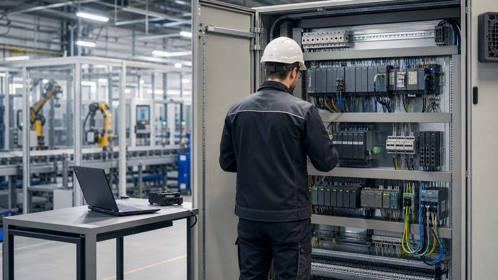
What does PLC modernization include?
PLC modernization is rarely limited to replacing one CPU. The project may include local and remote I/O, HMI panels, variable-frequency drives, servo systems, industrial networks, safety devices, SCADA communication and data exchange with higher-level systems. In some installations a complete platform replacement is appropriate. In others, retaining selected I/O stations or introducing migration adapters can reduce rewiring and shorten the cutover.
The correct scope starts with the business and operational objective. A controller replaced because spare parts are unavailable requires a different strategy from a project intended to improve diagnostics, prepare a machine for expansion or integrate production data. The target architecture should resolve the actual constraint rather than simply reproduce the legacy hardware with a newer catalogue number.
When should a legacy PLC be replaced?
A failure should not be the first trigger for a migration assessment. Planning is justified when one or more of the following conditions appear:
- the controller, I/O modules or operator panel are approaching the end of their supported lifecycle;
- there is no verified backup or editable source project;
- spare components are available only from uncertain secondary-market sources;
- the engineering software depends on unsupported operating systems, interfaces or licences;
- minor production changes require increasingly complex workarounds;
- diagnostics, alarm history or secure data exchange are insufficient;
- the plant is already planning changes to drives, HMI, networking or supervisory systems.
Early preparation creates time to recover missing information, order compatible hardware and test the application. It also separates work that can be performed while production is running from tasks that genuinely require the line to stop.
PLC migration plan: ten practical stages
1. Define the boundary and acceptance criteria
Establish which cabinets, machines, axes, networks and external systems belong to the project. Identify what will remain unchanged and where responsibility for each interface begins and ends. This prevents an apparently small controller replacement from expanding unexpectedly during commissioning.
Acceptance criteria should describe real process functions, not merely successful code compilation. Define the operating modes, sequences, alarms, interlocks, recipes, communication paths and production conditions that must be demonstrated. Agree on the maintenance window, decision-makers and the conditions under which the team will stop the migration and restore the previous system.
2. Survey the hardware, software and communication
Record hardware part numbers, firmware versions, rack configuration, module addresses and terminal assignments. The survey must extend beyond the main PLC to remote I/O, HMI, drives, safety controllers, barcode readers, printers, vision systems and any device that exchanges data with the controller.
Document network topology, protocols, IP addresses, fieldbus parameters, update cycles and the response to a lost connection. Compare electrical drawings with the physical installation. Service modifications made over many years are often missing from drawings, and one undocumented signal or network dependency can delay commissioning more than the controller replacement itself.
3. Create and validate recoverable backups
Back up the PLC program, HMI project, drive parameters, safety application, recipes and relevant device configurations. A file is not automatically a recoverable backup. Record the engineering-software version, libraries, firmware, option packages, licences and access credentials required to open, compile and download each project.
Keep an unchanged source archive, a working copy for conversion and independent exports of important tables. Where possible, test that the archive can be opened on a prepared engineering station. This provides a reliable baseline for both migration and rollback.
4. Build an accurate I/O list and interface matrix
The I/O list should connect each logical address with its terminal, signal type, field device, program function and expected safe state. The interface matrix should identify the source and destination system, protocol, data structure, handshake, update rate and behaviour after communication loss.
These documents support hardware selection, code conversion and test preparation. They also expose unused, duplicated or poorly described signals before the maintenance window begins.
5. Select the target architecture and migration method
Size the new platform for the process requirements: program load, scan time, I/O quantity and type, motion functions, functional safety, redundancy, network capacity, diagnostics and long-term serviceability. A complete industrial automation system design should include architecture, device selection, drawings, I/O documentation, communication definitions and the commissioning strategy.
Common migration approaches include:
- single-stage replacement when the system is well documented and the shutdown window is sufficient;
- phased migration when individual sections can be transferred and accepted separately;
- parallel construction of a new cabinet so wiring, configuration and testing can be completed away from the machine;
- retaining compatible I/O or field wiring with documented adapters when this reduces site work without creating an unsupported mixed system.
6. Convert the application and prepare an offline test system
Program conversion between controller generations is not fully automatic. Memory organisation, data types, timers, fault handling, technology blocks, addressing and communication libraries may behave differently. Compile the converted application, resolve warnings and compare each critical function with the source system.
Perform as much validation as possible away from the production line. A PLC–HMI test rack, signal simulation or a software model can verify sequences, alarms, interlocks, recipes and communication failures. The goal is to use the shutdown for physical changeover and final process confirmation—not for faults that could have been found at a desk or test bench.
7. Complete a documented FAT
The Factory Acceptance Test should contain test cases, expected results, actual results and approval responsibility. It should cover critical automatic sequences, manual modes, alarm handling, HMI functions, communication, restart behaviour and prerequisites for site commissioning.
Record and resolve deviations before deployment. A structured FAT also establishes a shared understanding between automation engineers, maintenance, production and the project owner.
8. Prepare the cutover runbook and rollback plan
The cutover runbook defines the exact order of work: controlled process shutdown, energy isolation, wire identification, removal, installation, connection checks, software download, power-up and staged testing. Assign an owner and a decision checkpoint to every critical step.
A rollback plan is equally important. Define the latest decision point for returning to the legacy configuration, who can make that decision, how the previous hardware and software will be restored, and which tests will confirm safe recovery. The old equipment, verified backups and required tools must remain available until the new installation has passed acceptance.
9. Execute SAT and a controlled production restart
The Site Acceptance Test validates the system on the real machine. Check field signals, drive directions, interlocks, safety circuits, sequences, alarms, HMI functions and communication with peripheral and supervisory systems. Progress from individual devices to manual functions, automatic operation and a controlled production batch.
Plan a monitoring period after restart. Review cycle times, communication diagnostics, recurring alarms and operating scenarios that could not be reproduced during FAT. Keep engineering support available until the agreed stability criteria are met.
10. Deliver complete as-built documentation
The project is not complete until documentation reflects the installed system. The handover package should include source projects, recoverable archives, electrical drawings, I/O lists, network addressing, firmware and software versions, parameter backups, recovery instructions and signed FAT/SAT records.
Agree on a future backup and change-control process. Without it, the next service intervention will again depend on reconstructing knowledge from the machine.
How can PLC upgrade downtime be reduced?
The most effective downtime reduction takes place before the line stops. Practical measures include:
- completing measurements, documentation and wire identification during earlier site visits;
- prefabricating and inspecting a new cabinet off-site;
- testing the PLC, HMI and communication on a prepared test system;
- dividing the cutover into independently verifiable stages;
- preparing cables, adapters, licences, tools and spare parts in advance;
- using one approved runbook and an unambiguous test list;
- maintaining a workable path back to the previous configuration.
The shortest shutdown is not automatically the lowest-risk shutdown. The objective is a short but controlled deployment window, supported by prior testing and completed by verification of every process-critical function.
Common mistakes during PLC replacement
- treating old electrical drawings as a guaranteed record of the installed system;
- backing up the PLC while overlooking HMI, drive or safety configurations;
- assuming an automated conversion will preserve every behaviour;
- missing devices that communicate only occasionally or during faults;
- testing only the normal sequence and ignoring failure scenarios;
- starting work without a defined rollback threshold;
- postponing as-built documentation until the commissioning team has left.
What determines PLC modernization cost?
The controller price is only one component. Cost depends on the number and type of signals, source-code quality, HMI and drive scope, safety architecture, communication protocols, test coverage, cabinet prefabrication, electrical work, commissioning conditions and required post-start support.
A reliable estimate therefore follows a technical assessment. Additional preparation may reduce the cost and risk of the production shutdown. In other installations, a phased migration across several planned windows may be the better commercial and operational choice.
FAQ: PLC modernization and migration
Can a PLC be replaced without stopping production?
A controller that directly operates a running machine normally requires a controlled stop for physical cutover and final tests. However, surveys, cabinet construction, application development, simulation and FAT can be completed beforehand to minimise the work performed during the shutdown.
Can a legacy PLC program be converted automatically?
Migration tools can accelerate conversion, but they do not guarantee identical system behaviour. Hardware configuration, program blocks, data types, communication, alarms, technology functions and fault response must be reviewed and tested.
What if the editable PLC source project is missing?
First determine whether a controlled upload from the running controller is possible and identify the required software version and access rights. If the recovered application is incomplete or cannot be edited, assess the effort required to reconstruct the logic before scheduling replacement.
What is the difference between FAT and SAT?
FAT is completed before installation and validates the prepared solution in a test environment. SAT is performed on the real machine after installation and confirms field I/O, equipment, sequences, safety functions and communication under site conditions.
Must every I/O module be replaced?
Not always. The decision depends on compatibility, lifecycle status, technical condition, spare-part availability and the migration strategy. Retaining selected I/O can reduce field work, but it should be supported by a documented risk and maintenance assessment.
Planning a PLC modernization project
SystemSmart delivers industrial automation systems, control-system modernization and integration of PLC, HMI, SCADA and field equipment. We begin with the existing installation, the available engineering data and the work that can be completed before production stops.
When preparing an enquiry, collect the available drawings, source backups, device list and information about possible maintenance windows. These inputs make it possible to compare migration options and define a realistic test and rollback strategy for the specific machine.
Technical references
- Siemens — Safe migration of automation systems — migration strategies, services and tools for SIMATIC automation systems;
- Schneider Electric — Using the Plant SCADA Migration Tool — guidance on creating a backup before migration and verifying the converted project.